Tel: +86-18874804206 E-mail: sales@innovequipment.com


- All
- Product Name
- Product Keyword
- Product Model
- Product Summary
- Product Description
- Multi Field Search
- Home
- Products
- ABOUT US
- News
- Application
- FAQ
- Contact Us
Views: 125 Author: Site Editor Publish Time: 2026-03-21 Origin: Site
In line with the rapid advancement of pharmaceutical machinery, pharmaceutical enterprises urgently require higher levels of automation and production efficiency. To meet these demands, Innov Equipment has successfully developed the NJP-800 closed-structure fully automatic hard capsule filling machine based on the proven NJP series platform.
This model incorporates breakthrough innovative improvements in mechanical structure, power control systems, vacuum systems, and dust collection, achieving multiple technical indicators that reach or exceed the advanced level of international counterparts. As a high-tech product integrating mechanics, electronics, and pneumatics, the NJP-800 is currently the most ideal and perfect capsule-filling solution for pharmaceutical production in its class.
By simply changing molds and related components, the machine can handle all standard hard capsule sizes (0# to 5#). It features GMP-compliant design, intermittent rotary operation, and precision perforated-disc metering for superior accuracy, efficiency, and cleanliness.

Production Capacity: 800 capsules/min (NJP-800C3 model; series configurable for 400 / 600 / 800 capsules/min) Power Supply: 380 V, 50 Hz, three-phase four-wire Total Power: 5 kW Overall Dimensions (L × W × H): 700 × 900 × (1,800 + 300) mm Weight: 800 kg Vacuum & Dust Collection Equipment:
Vacuum pump: 40 m³/h pumping rate (for capsule separation)
Dust collector: 300 m³/h pumping rate (for waste capsule and powder removal)
3.1 Installation 3.1.1 Machine Positioning Handle and place the machine gently to protect internal electronic components. Position the base on rubber pads for vibration isolation. Ensure the work surface is perfectly level with no rocking.
3.1.2 Environmental Requirements Ambient temperature: 21 ± 3 °C Relative humidity: 45–50 %
3.1.3 Auxiliary Equipment Installation Install the dust collector separately from the main unit to minimize noise.
3.1.4 Connect the dust collector hose to the main machine. 3.1.5 Connect the power supply, ensuring voltage matches the machine specifications.
3.2 Trial Run 3.2.1 Check all bolts, screws, nuts, and pins for tightness (to prevent loosening caused by transport vibration). 3.2.2 Insert the special handwheel onto the main motor shaft and manually rotate the machine for 3–5 full cycles. Verify smooth, coordinated movement of all parts. 3.2.3 Switch on the power and run the machine empty for 1–2 hours (refer to Section 6 for startup procedure).
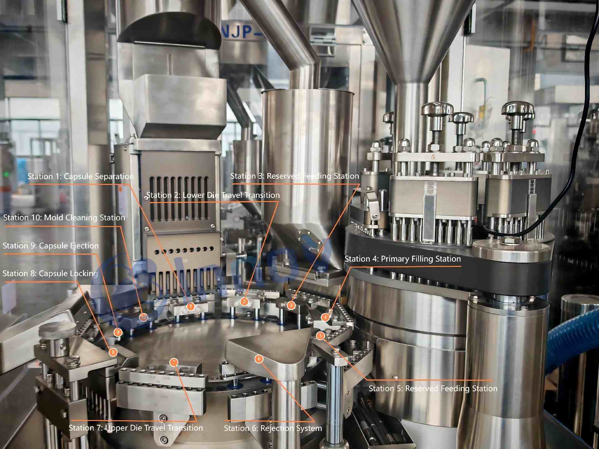
4.1 Working Principle The NJP-800C3 employs a precision indexing intermittent-motion capsule filling system. The working process follows the standard sequence of capsule feeding → separation → powder filling → locking → ejection → waste rejection (detailed diagram reference omitted in text version; visual process available in the machine’s HMI).
4.2 Main Structure 4.2.1 Mechanical Section (Figure 1) The machine is divided into upper and lower sections.
Upper working section: capsule feeding, stations, filling, hopper, rejection, locking, ejection, and suction mechanisms.
Lower section: transmission system including drive mechanisms, chains, and micro-adjustment brackets.
4.2.2 Pneumatic Section Vacuum pump separates capsule caps and bodies; industrial dust collector removes waste capsules and powder.
4.2.3 Electrical Section Uses international-brand components with a user-friendly touchscreen HMI, variable-frequency stepless speed control, and intelligent fault diagnostics.
The machine is factory-tested and pre-adjusted. Re-adjustment is required only when replacing capsule modules or performing thorough cleaning. Important: All adjustments must be performed with the main motor turned manually using the handwheel only.
5.1 Mechanical Adjustments 5.1.1 Capsule Hopper Door Adjustment Adjust door height via locking nuts to maintain powder level at approximately ½ of the outlet height.
5.1.2 Pressure Spring Blade Adjustment Manually set insertion depth so each capsule tube receives exactly one capsule.
5.1.3 Capsule Feeding Tube Adjustment The tube performs reciprocating motion (feeding, storage, ejection, pushing). Adjust the lower tie-rod (double-threaded) to maintain 2–3 mm clearance between capsule combs.
5.1.4 Vacuum Separation Device Adjustment Set vacuum slider gap to lower mold at 0.8–1 mm (non-working position) via tie-rod for reliable cap/body separation.
5.1.5 Upper/Lower Mold Alignment (Figure 9) Upper mold performs vertical circular motion; lower mold performs telescopic circular motion. Maintain 0.3–0.5 mm clearance. Use two alignment pins for concentricity of 0.01–0.02 mm. The station uses a fully sealed modular design (patented), allowing mold cleaning without full disassembly.
5.1.6 Dosing Disc & Sealing Ring Clearance Target clearance: 0.03–0.08 mm. Loosen screws, rotate adjustment bolts, use feeler gauges, then re-tighten. Clean periodically after extended operation (refer to 8.1.2).
5.1.7 Powder Blocker Clearance Target: 0.05–0.1 mm. Adjust via locking nut and screw, verify with feeler gauge.
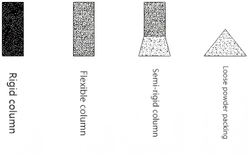
5.1.8 Powder Level Sensor Adjustment Capacitive sensor controls powder height in the hopper. Adjust height according to capsule size and powder flowability for precise dosing. Sensitivity screw allows 2–8 mm detection range.
5.1.9 Filling Rod Height Adjustment (Figure 8) Rod penetration depth into the dosing disc controls dose and powder column density. Rotate handwheel to lowest position, set zero reference, then adjust per the table below (for 18 mm disc thickness):
Station | 1 | 2 | 3 | 4 | 5 |
|---|---|---|---|---|---|
Insertion Depth (mm) | 9 | 5 | 3 | 2 | 0.5 |
5.1.10 Defective Capsule Rejection Adjustment Adjust tie-rod so the ejector plane maintains 1.5–2 mm clearance with the upper mold lower plane.
5.1.11 Capsule Locking Adjustment After filling, rotate tie-rod so the pin rises to a height equal to the locked capsule length (verify with unlocked capsules in front-row holes).
5.1.12 Capsule Ejection Adjustment (1) Raise ejector pin 1–2 mm above upper mold plane at high position; ensure it stays below lower mold plane at low position. (2) Adjust the inclined △ guide slot angle and height for smooth capsule discharge.
5.1.13 Safety Clutch Adjustment Tighten nut if slippage occurs after prolonged operation (prevents overload).
5.1.14 Transmission Cam Adjustment Factory-set; do not readjust unless necessary. Follow Figure 21 for precise angle and position.
5.1.15 Transmission Chain Adjustment Re-tension using the tensioner wheel and lock with nut (new mechanism for improved longevity).
5.1.16 Vacuum Level Adjustment Water-ring vacuum pump ensures accurate capsule feeding and separation. Adjust valve to maintain 0.03–0.08 MPa (read on gauge).
5.1.17 Dust Collector Regularly clean filter mesh to prevent clogging.
6.1 Touchscreen Operation Guide 6.1.1 Main Screens a. Home screen – tap “SK” logo to enter next screen. b. Password screen. c. Operation menu (6 function keys). d. Auto Operation screen – displays speed, output per minute, total count. Start auto mode; manual buttons reset automatically. e. Parameter Setting screen – select feeding mode, set auto-feed delay (10–20 s), starvation stop (30–40 s), or timed feeding. f. Manual Operation screen – independent keys for setup and debugging. g. Fault Display screen – 5 alarm points; auto-pops, sounds alarm, and stops machine. Auto-resets after fault clearance (starvation alarm includes delay stop). h. Maintenance screen. i. Door Status – 4 doors with sensors; machine cannot start in auto mode if any door is open.
6.1.2 Feeding Control & Timing
Auto feeding: controlled by level sensor (SQ1).
Manual feeding: via manual screen.
Timed feeding: set in parameter screen.
6.1.3 Operation Steps a. Pre-start: manual handwheel rotation (1–3 cycles), then power on and start touchscreen. b. Use manual mode first for testing; switch to continuous auto only after verification. c. Speed Control (Figure 25-4): ▲ increase frequency, ▼ decrease. Limit to ≤40 Hz during first 100-hour run-in period. d. Emergency Stop: Press SB0 (self-locking); rotate arrow direction to release.
Regularly clean all powder-contact parts (hopper, dosing disc, powder box, powder remover, upper/lower molds, pins, etc.) with alcohol. Do not use gasoline, kerosene, ether, or acetone. Clean when changing products or after long idle periods. 7.2 Remove oil residue under the table for clear visual inspection. 7.3 Replace vacuum pump circulating water periodically; check filter if vacuum is insufficient. 7.4 Machine Lubrication a. Apply grease to cam rollers weekly. b. Lubricate all platform bearings weekly. c. Clean and grease bearings regularly; use oil for sealed bearings. d. Check and lubricate transmission chain weekly. e. Inspect 10-station and 6-station indexing boxes monthly; top up oil; replace every 6 months. f. Indexing boxes must be serviced only by qualified technicians.
To change capsule size (0#–4#), replace the following parts (manual rotation only during replacement/debugging):
Upper/lower molds, filling rods, dosing disc, capsule feeding tubes, capsule combs, etc.
8.1 Replacement Procedure 8.1.1 Filling Rods (54 rods in 6 groups) – loosen pressure plate, remove groups, replace, realign tops to same plane. 8.1.2 Dosing Disc – remove powder blocker plate, replace disc and powder ring, reinstall rods, adjust depth, tighten. 8.1.3 Upper/Lower Molds (Figure 9) – use alignment pins in dosing holes for precise concentricity, tighten screws. 8.1.4 Capsule Feeding Tube Assembly (Figure 2) – remove hopper, raise assembly, replace combs and forks, ensure perfect alignment with mold holes and center feeding, reinstall hopper.
After all replacements, manually rotate the main shaft 3–5 full cycles. Confirm smooth motion of all station components with no interference. Only then start the machine (slow → fast speed).
Innov Equipment – Providing global customers with GMP-compliant, efficient, and precise capsule filling solutions. For service, spare parts, or technical support, please feel free to contact us.
This optimized English manual features clearer structure, professional terminology, consistent formatting, corrected numbering, and enhanced readability while fully preserving original technical content. All Innov Equipment branding elements (GMP emphasis, high-efficiency design, intermittent rotary precision) have been seamlessly integrated for authenticity and market relevance.


